MS240FA Two-Axis Four-Light Pod

The MS240FA two-axis four-light electro-optical pod consists of an uncooled infrared thermal imager, a 30x continuously zoom visible light camera, a laser illuminator, a laser rangefinder, a two-axis servo-stabilized platform, and an image processing component (autonomous recognition and tracking) . It features high precision and long operating range, and can be applied to medium and small-sized UAVs to perform day and night reconnaissance and surveillance missions over target areas.
The optoelectronic pod uses an uncooled infrared thermal imager and a visible light camera to detect, identify, and track ground targets around the clock, while simultaneously outputting infrared and visible light video in real time for mission personnel to view.
The pod has been adapted to several mainstream flight control platforms in China, enabling seamless integration with flight control systems; it can also be connected to the ViewControlStudio display and control software platform of our organization, assisting the overall unit in quickly completing the development of the UAV system.
This optoelectronic pod is mainly used in scenarios such as reconnaissance, border patrol, personnel search and rescue, and forest fire prevention.
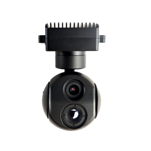
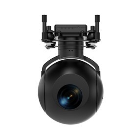
I. Photos of the actual product

Figure 1 Product Image
II. Product Functions
a) It has the function of automatic identification and tracking of typical targets;
b) It has self-testing and fault reporting functions;
c) It has a 30x optical zoom function for visible light ;
d) Possesses long-wave infrared and visible light band detection capabilities, and can output infrared images and high-definition visible light images;
e) Equipped with laser illumination and laser ranging functions;
f) Possesses the ability to move with two degrees of freedom: azimuth and pitch;
g) It has multiple working modes such as automatic search , manual search, follow-up, attitude stabilization, tracking, and guidance;
h) It has the function of isolating aircraft disturbances and stabilizing the line of sight with the two frames of azimuth and pitch;
i) It has the function of locking /unlocking targets, and the pod outputs an image with a tracking frame after locking the target;
j) It has target tracking capabilities, can automatically track targets, and is resistant to natural disturbances;
k) It has a memory tracking function, which allows the target to be recaptured in a short time after being briefly lost;
l) It has the function of adjusting the gate size;
m) Features tracking point switching functionality;
n) Infrared technology has two polarity switching functions: black-hot and white-hot, and also has image enhancement capabilities;
o) It has the function of real-time output of frame angle and angular velocity;
p) It has video compression, storage, and retrieval functions, and supports the H.264 format;
q) It can communicate bidirectionally with the control station via RS422 and output information such as infrared images, visible light images, system working status, camera working status, and optical axis position;
r) Equipped with an SDI video output interface;
s) Visible light has optical zoom, autofocus, manual focus and low light functions;
t) It adopts an integrated design, is lightweight, easy to adjust, and has strong impact resistance;
u) Equipped with photo and video recording functions;
III. Mounting Platform
Vertical take-off fixed-wing drones, rotary-wing drones, tethered drones, etc.
IV. Main Technical Parameters
| model | S240FA |
| Infrared thermal imager | |
| Detector type | Uncooled focal plane detector |
| Operating band | 8μm~14μm |
| Detector resolution | 640×512 |
| Pixel size | 12μm |
| Lens focal length | 25mm to 100mm continuous zoom |
| Field of view | 17.5º×14.0º~4.4º×3.5º (error≤5%) |
| Pseudo-color | 10 types |
| Numbers multiplied | 1~4X |
| Noise equivalent temperature difference | NETD≤40mK |
| Minimum distinguishable temperature difference | MRTD≤500mK |
| Visible light camera | |
| resolution | 1920×1080 |
| Response band | 0.4μm to 0.9μm |
| Pixel size | 2.8μm |
| Optical zoom | 30 times |
| Mixed Variable Multiplication | 60 times |
| focal length | 4.3mm~129mm |
| Field of view | 63.7°×35.8°~2.3°×1.3°(±5%) |
| zoom mode | Autofocus, manual focus |
| Minimum Illumination | 0.01 Lux (Black and White) |
| laser illuminators | |
| wavelength | 808±5nm |
| Maximum lighting distance | ≥2km (under conditions of visibility ≥15km) |
| Spot diameter | Far angle 0.8°: effective distance ≥2000m, spot diameter 28m;Near angle 70°: effective distance ≥40m, spot diameter 56m; |
| lighting angle | Electric synchronous zoom, continuously adjustable from 0.8° to 70°. |
| Double Time | ≤3 seconds (far angle – near angle) |
| Laser output power | ≥12W |
| Laser rangefinder | |
| wavelength | 1535nm |
| Maximum ranging distance | ≥6km (visibility ≥15km) |
| Minimum ranging distance | ≤20m |
| Distance measurement accuracy | ≤2m |
| Ranging frequency | 1~5Hz |
| Servo Platform | |
| Orientation angle | 360°×n (360° continuous rotation) |
| Pitch angle | -120°~+20° (positive for upward) |
| Frame corner accuracy | ≤0.06°(1σ) |
| Stable accuracy | ≤0.05mrad (1σ) |
| Angular position accuracy | ≤1mrad (1σ) |
| Maximum turning speed | Azimuth ≥ 60°/s, Pitch ≥ 60°/s |
| Maximum turning acceleration | Azimuth ≥ 100°/s², Pitch ≥ 100°/s² |
| System Indicators | |
| Image tracking | Automatically track selected target |
| AI recognition | Automatic detection and identification of typical targets |
| Rated operating voltage | 24VDC |
| Power supply voltage range | 20V to 32VDC |
| power | Stable power consumption: ≤100W; Peak power consumption: ≤200W |
| weight | ≤9.5Kg |
| volume | ≤240mm×240mm×330mm |
| Continuous working time | ≥8h |
| Image recording time | ≥8 hours (simultaneous recording of two video streams) |
| Image frame rate | ≥25Hz |
| interface | |
| Control Interface | RS422 |
| Video interface | HD-SDI/100Mbps Ethernet (H.264) |
| Storage interface | ≤128G memory card (Mini SD card) |
| Image format | JPG format |
| Video format | AVI format |
| Environmental adaptability | |
| Operating temperature | -40℃~+60℃ |
| Storage temperature | -50℃~+70℃ |
| Vibration conditions | The acceleration is 2g; 30 minutes each in the vertical, horizontal and longitudinal directions. |
| Impact conditions | Peak acceleration 20g, duration 11ms |
| Protection level | Can fly in light to moderate rain |
V. Mechanical Dimensions and Installation Interfaces


Figure 2 Product mechanical dimensions diagram